Flux Reference Manual

  • Welcome to Flux
  • Introduction
    • Installing the Software
    • The User Interface
    • Part Workflow
    • The Machine Database
  • Cut
    • Basic Workflows
      • Part Workflow
        • Load Part
        • Sketch Mode
        • Measure
        • Modifying Laser Part
        • Nesting
        • Sequence Navigator
        • NC Code Generation
      • Job workflow
        • Create Job
        • Set Laser Technology Table (LTT)
        • Nesting
        • Automatic Part Placement
        • Manual Part Placement
    • Advanced Topics
      • Geometry Import Options
      • Advanced Tooling Options
        • Editing Microjoints
        • TwinLine
        • FlyLine
        • Dimple Approach
        • Remainder Sheets
        • Pie-Slug Circular Holes
        • Avoid Retooling Pierces
        • Finishing Rules
        • Clone LTT
      • Advanced Nesting Features
        • Mirrored Parts
        • Find a Part in Nest Layout
        • Filler parts in Nest Layout
      • Advanced Tooling Optimization
        • Contour Quality
        • Optimizing Stability with Scrap Cutting
        • Optimizing Tilting Behaviour
        • Space Out Slice Cuts to Avoid Collision
        • Minimize Number of Different Layouts
        • Dynamic Level Setting
      • Advanced Menu Options
        • Context Sensitive Menus
        • Hierarchy of Settings
        • Multi-Selections
        • CSV Output
      • Manual Sheet Slicing Cuts
      • Text on Parts
    • Application Settings
      • Cut CAM
        • Layout
          • Nest Settings
          • Sheet
          • Sheet Handling
          • Skeleton Cuts
          • Work Support
        • Laser CAM
          • Sequence
      • Cut Outputs
      • Cut View
  • Bend
    • Basic Steps of Flux Bend
    • Basic Workflow
      • The Main Panel
      • The Workflow Panel
      • Batch processing
      • Modifying the Geometry
      • The Bend Navigator
      • Editing the Bend Solution
        • Editing a Bend
        • Changing the Bending Sequence
        • Editing a Tool Mount
        • Editing a Bend Setup
        • Editing the Back-Gauges
        • Angle Measurement
        • Using a Pre-Bend
        • Editing multiple mounts
        • Adding a Tooling station
      • Recomputing the Bend Solution
      • Generating Bend Outputs
      • Export Bend Report
    • Design of bend parts
      • Min Radius and Flange Length
      • Corner Design
      • Bending Tolerances
      • Selection of Tools
    • Advanced Workflow
      • Preparation of Bend Parts
        • Preparing a 2D drawing
        • Editing a Drawing
        • Add Bending Information as Text to DXF
        • Measuring and changing Outer Dimension
        • Preparing 3D models
        • Preparing an Assembly
        • Component Detection
        • Form Detection
      • Edit Tools
        • Changing Tool Map
        • Change Tool Segmentation
        • Editing Tool-mount Segments
        • Adding a Gap into the Tool
        • Use a Double-V Adapter
        • Tool Priority
        • Creating a Tool
      • Using Bend Deductions
      • Control Visibility
      • Comment Section in Bend Panel
      • Tools/Machine Tonnage Check
    • Settings
      • Application Settings
        • Bend CAM
          • Bend Outputs
          • Bend View
          • Bend Cell
      • Database Settings
        • Materials
        • Machines
        • Bend Tools
        • Bend Deductions
        • Bend grippers
        • Forms/Components
      • Bend Settings
      • Machine Defaults
  • Robotic Bending
    • Overview of Robotic Bending
    • Basic Steps of Robotic Bending
    • Workflow
      • Part Pickup
        • Pickup from a Pallet
        • Pickup from a Dispenser
      • Insertion Strategy
      • Bending Strategy
      • Regripping (RG) Stations
        • Re-Grip Stations
        • Methods of Regripping
        • Adding ReGrip
        • Modify ReGrip Position
        • Remove ReGripping
        • Regrip with a Jaw Gripper
        • Gripper Panel & Suction Panel
      • Extraction Strategy
      • Part Deposit
        • Adapt Part Deposit
        • Adding Parts & Stacks
          • Deposit Panel
          • Add Separator Sheets
          • Lock Part-Rest
          • Repeat Grid Field
          • Deposit Sequence
        • Deposit Pattern Types
      • Waypoints
        • Adapt WayPoints
        • Display Waypoints
        • Simulate Waypoints
        • Modify WayPoints
        • Properties of Waypoints
    • Advanced Topics
      • Cell Configuration
        • Track Setup
        • Gripper Inventory
        • BendCell settings
      • Gripper Configuration
        • Create/ Edit a Gripper
        • Import Gripper from DXF
    • Troubleshooting Bend Errors
      • Part Pickup Error
      • Collisions with Machine
      • Overtravel of Axis
      • Modifications of Waypoints
      • Collisions while Insertion and Extraction
  • Fold
    • Switching to Fold CAM
    • The Fold View
    • Editing Operations
      • Editing a Bend-Op
      • Editing a Side/Section
      • Changing the Sequence
      • Editing the Blank-holders
      • Editing the Gauging
      • Editing the Blades
      • Editing the Loading
      • Editing the Unloading
    • Tool Management
    • Fold CAM Summary
  • Generic Application Settings
    • Drawing
      • Layers
      • Dimensions
      • View
    • Environment
    • Import/Export
  • Flux Reports
    • Report Designer
    • Fields, Pictures and Tables
    • Bands (sub-reports)
    • Labels, Bitmaps and Shapes
  • Appendix
    • Supported 3D Formats
    • Separator Sheet DXF
Bend
/
Advanced Workflow
/
Edit Tools
/
Creating a Tool

Creating a Tool

Flux Bend stand alone can export bending tools as a DXF or ARV format and can import bending tools from a DXF or ARV format. All tools can be exported as a DXF format. However, only single upper tools and single lower tools can be exported as an ARV format as ARV version 4.15, no Z-bend, adapters or holders. More tool-ARV-files can be imported than exported. ARV-import exceptions are complex special tools such as e.g: hinge tools.

To create a DXF file for a new tool, a DXF file of an existing tool must be processed:

  1. Export existing tool

  2. Open exported DXF file

newitem432
  1. The DXF file must contain the following:

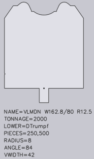
    1. A closed form (of lines, arcs, polylines) which shows the side profile of the tool. In the drawing, this form must be at the closed polyline that is furthest to the left.

    2. A point which marks the reference point of the tool. This point must be located somewhere inside the polyline of the closed profile and indicates the point from which the height of the tool is measured.

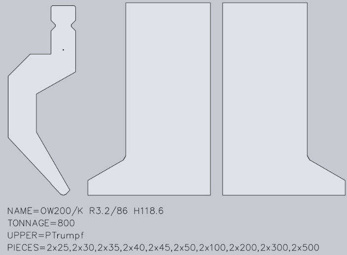
    3. A front view is required for each tool which is not a simple rectangle in the front. These are typically left or right horn tools, but can also be user-defined tools.

    4. Each front view drawing must appear on the right-hand side next to the sectional drawing, must be horizontally aligned and have the same height as the sectional drawing (currently, only the horn view is supported).

    5. Additional information about the tool is displayed using text stringsThe following text strings are recognized:

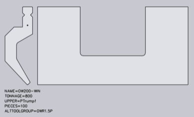
    6. NAME=UT200/K R3.2/86 CUSTOM-A (specifies the tool name; is required)

      1. TONNAGE=800 (specifies the maximum load of the tool in kN/m; this is required to avoid showing incorrect tool overload errors).

      2. UPPER=PTrumpf (specifies the connection type of the upper tool to the press beam; the following connection types are supported: PTrumpf, PAmada and PEHT).

      3. LOWER=DTrumpf (specifies the connection type of the lower tool; the following connection types are supported: DTrumpf, DAmada30, DAmada60, DAmadaF, DAmada2V, DAmadaQuick, DAmada90, DEHT and DAmada120)

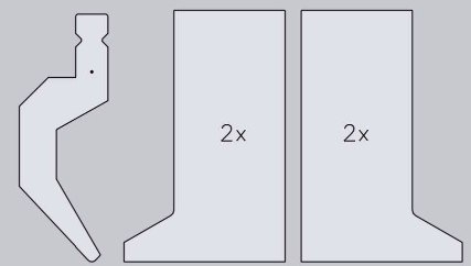
      4. PIECES=2x25, 30, 45, 50, 2x100, 200, 4x500 (this specifies the standard quantity for this tool, whereby the quantity for the left and right horn tool are defined by their sectional drawing. The list consists of a number of comma-separated quantities and, optionally, a quantity multiplier may be added in front of these. In this case the text states the following tool quantity: 2 pcs with 25 mm, 1 piece with 30 mm, 1 piece with 45 mm, 1 piece with 50 mm, 2 pcs with 100 mm, 1 piece with 200 mm and 4 pcs with 500 mm). If multiple tools with special forms (such as horn tools) are present, a text with the number of the quantity must be entered in the form:

newitem433

A front view can be added for window tools.

newitem434
  1. Export drawing

  2. Import

  3. Create tool ARV file for the import to the machine.

  4. Activate created ARV file in the machine.

Special tools:

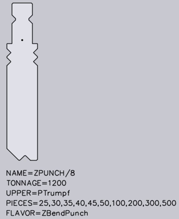
With Tool import, different types of special tools can be detected. These must be specified by a text in the form of FLAVOUR=XYX in the DXF file. Z-upper tools For a Z-upper tool, a text with the following format must be available in the DXF file: FLAVOR=ZBendPunch. The tool should be drawn so that the medium flat span width runs from left bottom to right top:
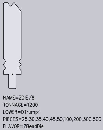
newitem435

Z-lower tools:

For a Z-lower tool, a text with the following format must be available in the DXF file: FLAVOR=ZBendDie. The tool should be drawn so that the medium flat span width runs from left bottom to right top:
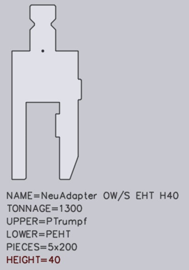
newitem436

Upper tool adapter:

For an upper tool adapter, a text with the following format must be available in the DXF file:

  1. A text such as UPPER=PTrumpf identifies the upper mounting type (PTrumpf is used if the adapter is mounted on a Trumpf machine).

  2. A text such as LOWER=PEHT identifies the bottom mounting type, either type of upper tool which is mounted on the adapter.

  3. A text such as HEIGHT=64 indicates the effective working height of the adapter. This is necessary because Flux Bend does not automatically detect the height of the adapter.

newitem437
Figure 1. Holder
newitem438

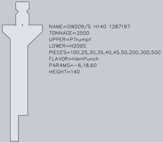
Holders are configured in exactly the same way as an upper tool adapter. However, certain holders, for example UT209/S, are also folding tools which are used to press down a fold. For these special holders, additional texts must be contained in the DXF file:

The text SPLFLAVOR=Hem. Punch identifies the adapter as a folding tool.

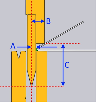
The text PARAMS=-6,18,60 identifies three parameters required for the correct simulation of the folding process. These parameters will be marked in the image below as (A), (B) and (C):

The first parameter (A) defines how far the flat vertical area of the tool is located behind the bending line. In this case, the value is negative, because the flat vertical area is located in front of the bending line.

The second parameter (B) defines how far the peak of the fold is located in front of the bending line.

The third parameter (C) defines the vertical clearance from the punching peak to the folding peak point.

newitem439
Figure 2. Special lower tools

Flux Bend shows messages such as Radius not specified or Angle not specified if the shape cannot be analyzed and the V-width, radius, angle etc cannot be detected as a result. In this case, the radius, angle and V-width must be added as a text.

newitem440
Tool Priority Using Bend Deductions

      Copyright © 2023 by Metamation. All rights reserved.

    Compiled by Bento